
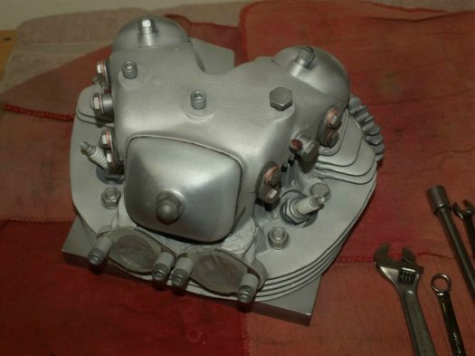
This article is a work in progress and will eventually address all the work and parts that may go into rebuilding a cylinder Head.
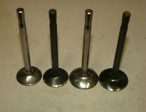
Old Britts stocks two manufacturers of valves for Norton Commandos. Both stock 750cc and 850cc engines use the same size intake valves and exhaust valves. We stock valves from Andover Norton and Kibblewite Precision Machining, Inc. (Black Diamond Valves).
All sizes in the following table are in inches and all prices listed are current as of 02/12/21.
| Part No. | Type | Manufacture | Head Dia. | Stem Dia. | Length | Price |
| 06-5115 | Exhaust | Andover | 1.303 | 0.311 | 4.020 | $34.70 each. |
| 06-5115/P | Exhaust | Kibblewite | 1.300 | 0.3107 | 4.015 | $34.98 each. |
| 06-5115/P6 | Exhaust | Kibblewite | 1.360 | 0.3107 | 4.005 | $34.98 each. |
| 06-4034 | Intake | Andover | 1.488 | 0.311 | 4.070 | $35.89 each. |
| 06-4034/P | Intake | Kibblewite | 1.500 | 0.3107 | 4.065 | $34.98 each. |
| 06-4034/P6 | Intake | Kibblewite | 1.560 | 0.3107 | 4.055 | $34.98 each. |
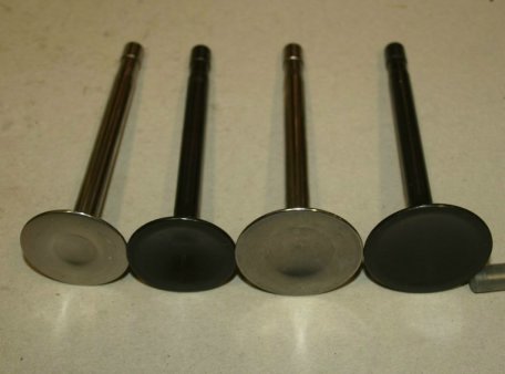
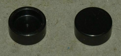
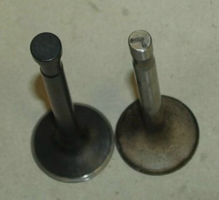
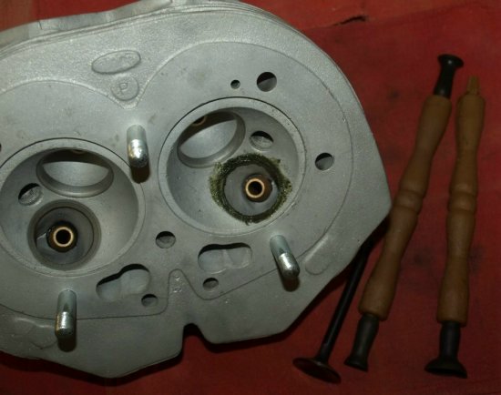
The purpose of using lash caps is to protect the top of the valve stem, allowing the replacement of the lash cap if they get pitted and providing a larger foot print for the valve adjusters. As you can see in the second picture the used valve has pitting caused from the valve adjuster rubbing across the valve stem.
The lash caps we use are from Kibblewite Precision Machining, Inc., part number 11-700816, $9.35 each.
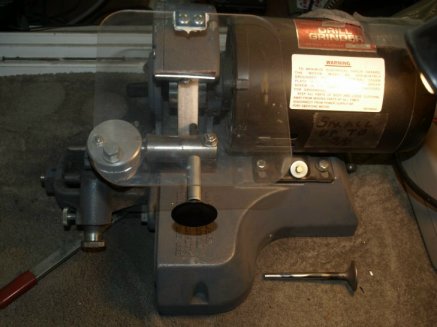
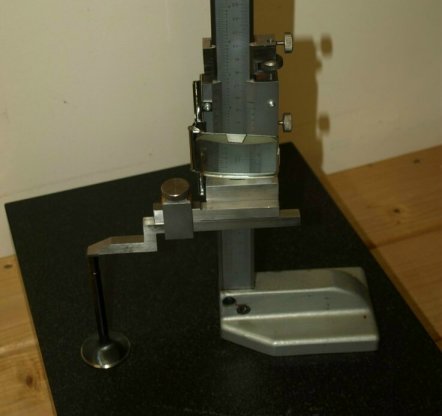
The lash caps extend the valve stem by .078" requiring the valve stem to be shortened by that amount. The lash caps should be able to rotate on the valve stem so they can be removed and installed when the valve is installed in the head. We can grind down a set of four valve stems for our lash caps, part number 11-700816/MV, $100.00. We check the length of the ground down valve with and without the lash cap installed.
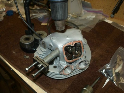
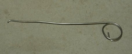
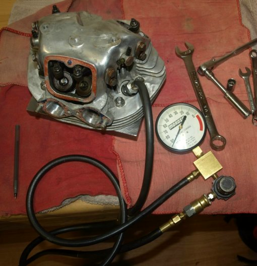
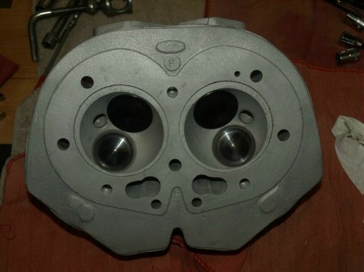
I check the valve leakage prior to dismantling the head for a point of reference. In the following picture the left side registered 8% leakages and the right side around 95%. This told me that the valve seats were probably fine and all I needed to do was lap in the new valves. After lapping the valves I did achieve 0% leakage for all four valves. With the head bolted to a bottom plate it is possible to achieve 0% leakage, since only the valves are being tested not the valves and pistons.
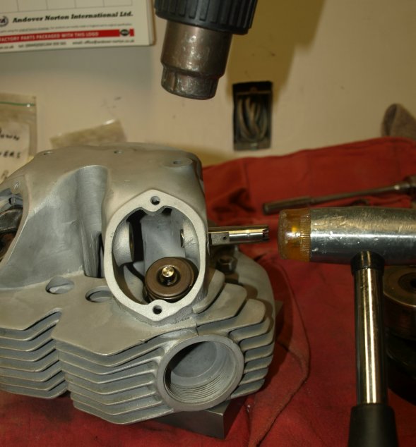
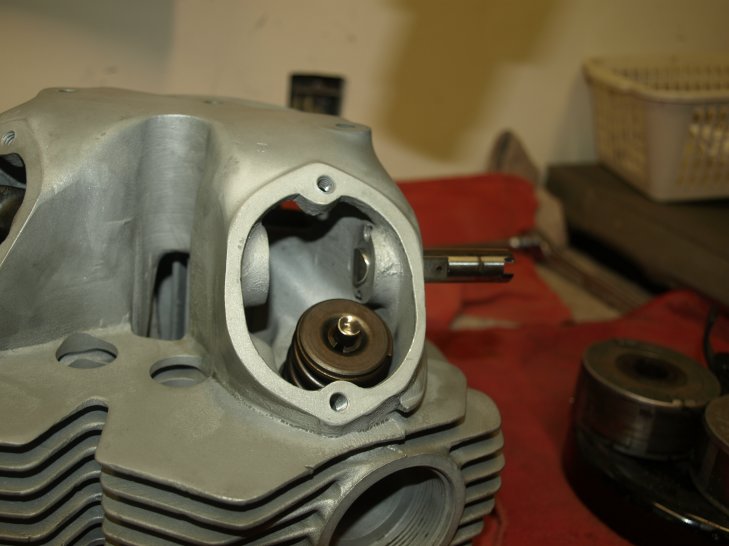
I use two types of lapping compound, Course and Fine. I use the course first then use the fine. I use a small brush to apply the compound to the valve seat.
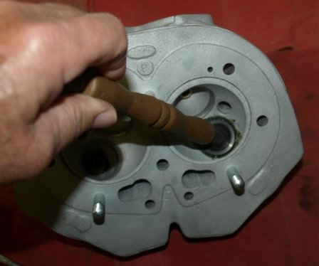
You can use a suction lapping stick to manually rotate the valve in the seat.
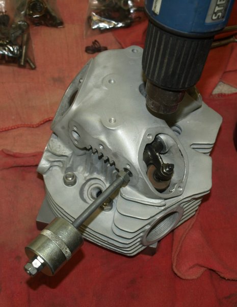
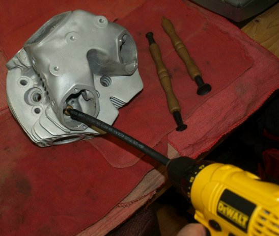
I use a drill attached to the valve stem by a rubber hose to turn the valve in the seat.
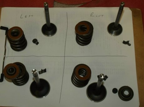
You need to keep the valves with the seats that you have just lapped so they go together when assembled.
This page was written and designed by F. H. Eaton
& Associates if you have any questions or comments please
contact us at infon@fheaton.com